.jpg)
Testing Speedometer Signals
Testing for a Speedometer Signal (Download PDF)
One of the most common tech calls at Classic Instruments starts with, “My electric speedometer is not working!” Once power and ground to
the instrument are verified, the next step is to determine if the speedometer is receiving a signal. With the flexibility of electric speedometers come many options for signal sources, each with its own method for testing. Testing can become complex with fancy electronic testing units, but a simple multimeter is all that is needed to verify that a signal is present.
Follow along with the guide below to determine what type of speedometer signal is present, and learn how it is tested.
1. Determine the signal source.
Generally most speedometer signals will be one of three types, for
simplicity, we will call them one-wire, two-wire, and three-wire.
One-wire signals are typically found in late model computer
controlled transmissions or fuel injected applications. This single
wire is the signal wire.
Two-wire sensors are present in many manual transmissions,
aftermarket cruise control, or older electronic speedometer kits.
They have two wires, one is the ground wire and the other is the
signal wire. The two wires can be reversed.
Three-wire signals are usually found in newer aftermarket
speedometer kits and they have three wires. One wire is a reference
power, one wire is the ground, and the third wire is the signal.
2. Use a mulitmeter to test.
One-Wire Signals. (Figure 1.)
Most one-wire signals can be measured with a multimeter set to DC
volts. Depending on the application, the reference voltage is usually
12 or 5 volts, and the signal measured will be approximately half of
that when the vehicle is moving. At rest, the voltage present will be
either the reference voltage or 0 volts. If there is no change in voltage
or no voltage at all when the vehicle is moving, there is not a signal.
A few notes to consider when using a one-wire signal source
- Some engine computers do not require a speed sensor input
to run. There must be a speed sensor (usually a two-wire)
connected to the engine computer to get the speed signal
from the computer.
- Often times, a re-worked factory computer has the
speedometer function stripped, use the test above or consult
the ECU provider/tuner to see if this function is present.
- Most standalone transmission controllers provide a clean
electric speedometer signal that can be calibrated within the
controller itself with the rear end ratio and tire size inputs.
- Many factory computer signals are considered “dirty” or have a
lot of ignition interference present. A speedometer filter may be
needed to clean the signal to a point that a speedometer can
process the signal. Filter part no. SN79.
- Some factory computer signals either put out a really fast or
really slow signal that is out of range for electric speedometers,
an additional interface may be needed. Part no. SN74Z.
Two-Wire Sensors. (Figure 2.)
The two-wire sensor works by generating AC voltage. The faster
the sensor is spun or triggered, the more voltage is generated.
Some two-wire senders have a shaft that is spun by a speedometer
gear (Part no. SN96 & SN95) and some have a toothed wheel
that spins next to a no-contact sensor (found in many Tremec
transmissions or factory VSS).
Spin the sensor or drive the car with a multimeter set to VAC
and connected to the two leads. At rest, the sender will produce
0 volts AC and this reading will increase with speed.
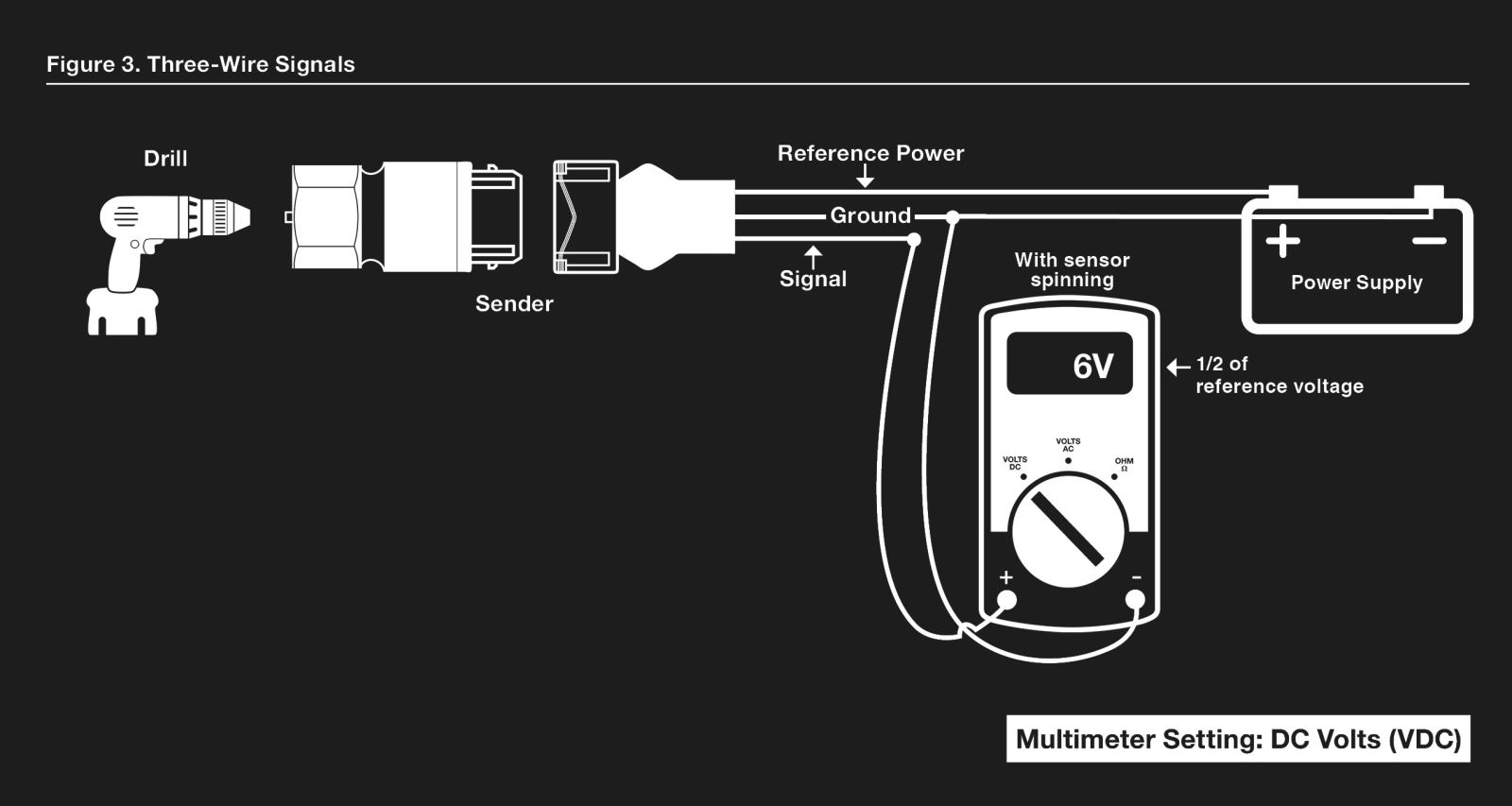
Three-Wire Signals. (Figure 3.)
The three-wire sensor (Part no. SN16) works by switching (pulsing)
a reference voltage on and off as the sensor spins. This switching
is fast, usually 8 or 16 pulses per revolution of the sender. The
switching happens fast enough that it will register on a multimeter
as approximately one half of the reference voltage since the “switch”
is only on half of the time.
Spin the sensor with a drill and measure the voltage on the signal
wire. If it is not approximately one half of the reference voltage, the
sensor is defective.
Click image to increase size.
Additional Questions?
Please call tech support 844-342-8437